





Milling Processes in Woodworking
Face milling, profile milling, conventional milling, CNC —there are many terms circulating in the world of milling, and they’re often thrown together haphazardly: processes, machines, and control systems all get lumped together, even in catalogs. Anyone who then chooses the wrong process or feed direction will end up with tears and burn marks—or, in the worst case, a workpiece that is yanked right out of their hands.
This article clarifies the terminology. You’ll learn about the different milling methods and how they differ, why CNC milling isn’t a separate method in itself, what conventional and climb milling mean—and how to determine which method is right for your project. Most of this applies to any machine: a router, a spindle moulder, or a CNC machining center.
Table of Contents
- Definition
- Overview of Milling Processes
- Process, Machine, Control System
- Subdivision
- Milling Processes in Detail
- Milling Methods by Direction of Travel
- What Matters in Milling
- Which method is best for what?
- FAQ
Definition: What are milling processes?
Milling is a machining process: A rotating tool, usually with multiple cutting edges, removes material from the workpiece. The cutting motion is circular, while the feed motion runs perpendicular to the axis of rotation—this distinguishes milling from drilling, in which the feed is directed along the axis. With each revolution, each cutting edge plunges into the wood and then withdraws. This intermittent cutting action produces the characteristic milling noise—and explains why sharpness, rotational speed, and feed rate have such a significant impact on the surface finish.
A “milling process” is a specific type of milling—classified based on the surface to be created, how the tool engages the material, and the relationship between the direction of rotation and the feed direction. Milling is used on wood, metal, and plastic. In woodworking, milling is the method used for almost anything that goes beyond a straight cut: profiles on edges and moldings, grooves and rebates, wood joints, flat surfaces on workpieces that won’t fit through a planer, and free-form shapes in furniture, interior design, and window construction.
Overview: What are the different milling methods?
The DIN 8589-3 standard classifies milling into six processes based on the surface to be produced: face milling, cylindrical milling, thread milling, gear hobbing, profile milling, and form milling. Thread milling and gear hobbing produce threads and gears—that’s the world of metalworking. For the woodshop, four methods remain, plus an application group with its own name:
- Face Milling – Creating Flat Surfaces
- Profile Milling – The Contour Is in the Tool
- Form Milling – The Shape Is Determined by the Feed Motion
- Circular Milling – Cylindrical Surfaces and Curves
- Joint Milling – Finger Joints, Tongue and Groove, Counter Profiles
CNC milling and 3D milling are intentionally omitted from this list—the next section explains why.
Process, machine, control system—three levels that are often confused
Much of what is commonly referred to as “milling” in everyday language is, strictly speaking, not milling at all. It helps to distinguish between three levels:
- The process describes what happens to the workpiece: a flat surface is created (face milling), a profile (profile milling), a free-form shape (form milling), or a cylindrical surface (cylindrical milling).
- The machine describes what you're working with: a router, an edge trimmer, a spindle moulder, a router table , or a CNC machining center. Each of these machines is capable of performing multiple operations.
- The control system determines who controls the feed motion: your hand, a mechanical feed device, or a computer program (CNC, “Computerized Numerical Control”).
“CNC milling” is therefore not a distinct milling process in itself, but rather a type of control system: the processes involved—such as face milling, profile milling, or form milling—are still carried out, only now they are computer-controlled. And “3D milling” is workshop jargon for form milling with controlled movement along three axes. If you distinguish between the three levels, you’ll be able to read catalogs and data sheets much faster—and realize that the fundamentals are the same for a router as they are for a machining center.
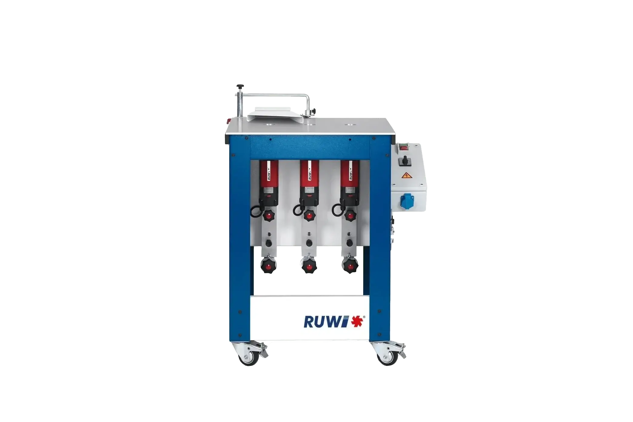
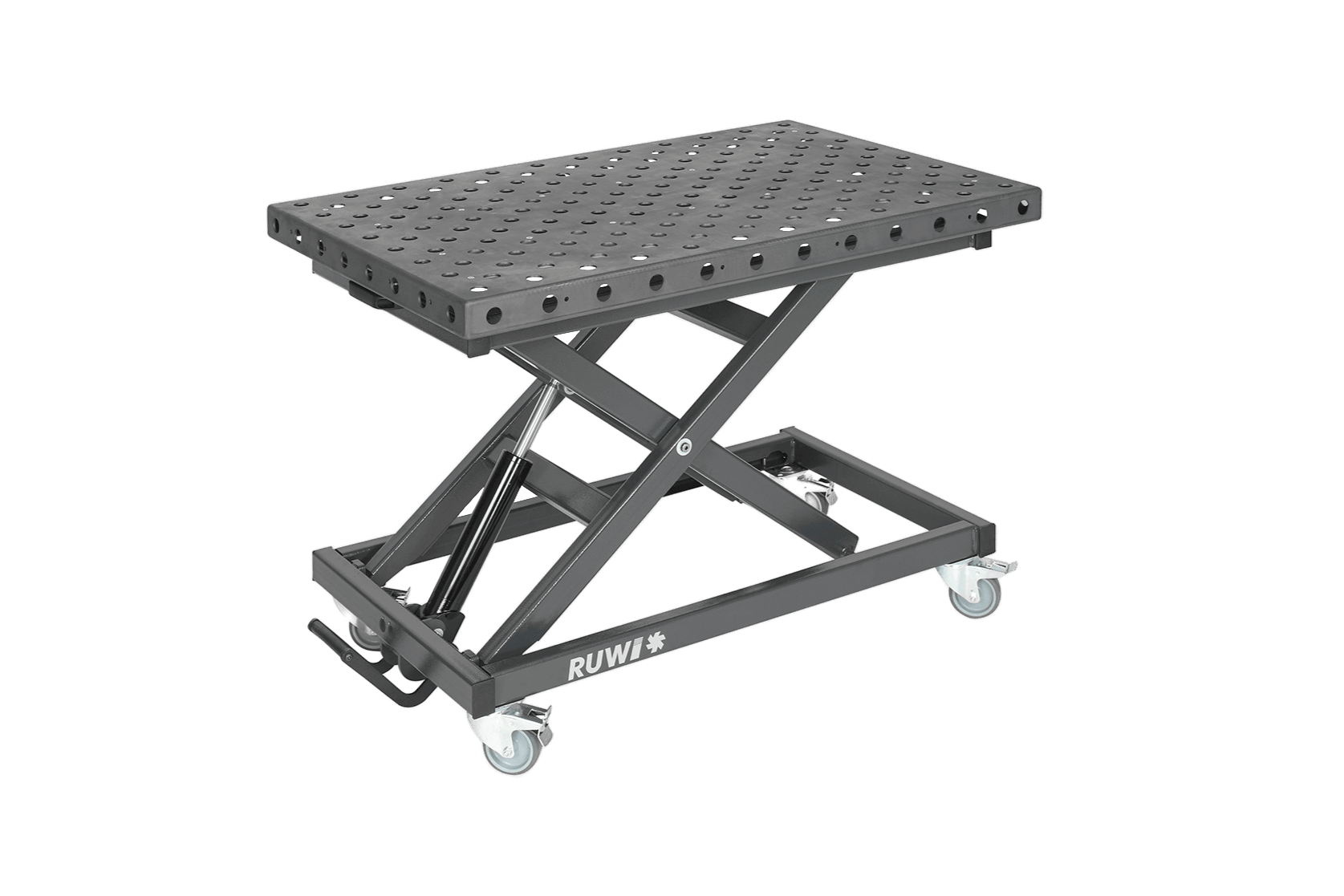
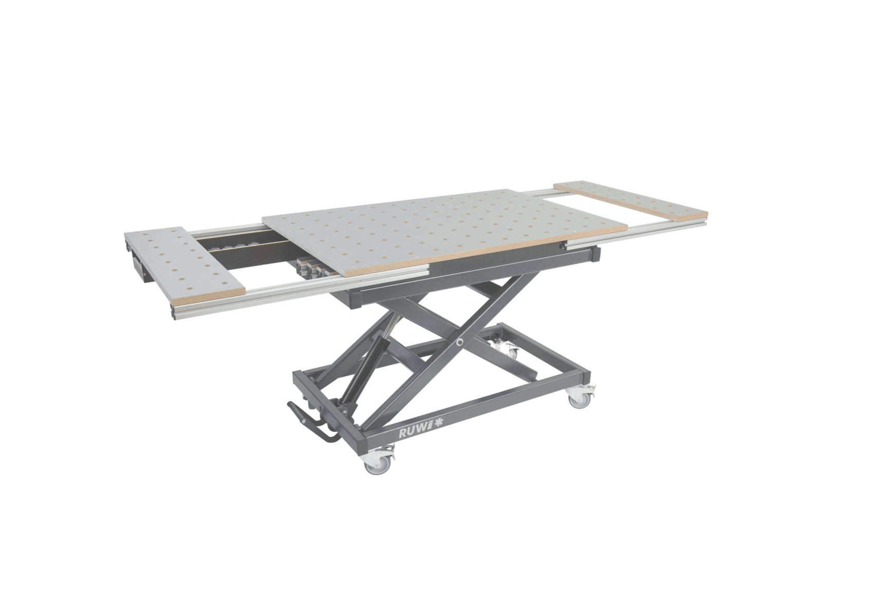
Tip: Between handheld and bench-mounted machines lies semi-stationary operation: The RUWI router table is a mobile router table—the routing work moves from the freehand-guided machine to a stable table with a stop.

Milling on RUWI router table
How are milling processes classified?
The topic is organized into three categories. You’re already familiar with the first one from the overview: the surface to be created—flat, round, contoured, or free-form. There are two more:
By tool engagement. In peripheral milling, the cutting edges work along the circumference of the tool, and the machined surface lies parallel to the axis of rotation—this is how edge profiles and rebates are created on a spindle moulder. In face milling, the end face of the tool cuts, and the surface is formed perpendicular to the axis—this is how a face mill works. When grooving with a shank cutter, both the circumference and the face engage simultaneously: face-and-peripheral milling.
Based on the direction of feed. The terms “conventional milling” and “climb milling” describe the relationship between the tool’s direction of rotation and the direction of feed. This distinction is critical for safety during manual feed—which is why it is covered in a separate section below.
A Detailed Look at Milling Techniques in Woodworking
Face Milling
In face milling, an uneven surface is removed in overlapping passes until it is flat. In woodworking, this is the method of choice for workpieces that won’t fit through a planer or thicknesser—because they’re too wide, too irregular, or not quite rectangular: tree slices, wide laminated panels, end-grain surfaces. The key is a small depth of cut per pass and cleanly overlapping passes; sanding takes care of the rest.
Profile Milling
In profile milling, the contour is embedded in the tool: The cutting edge carries the profile as a negative image, and a single pass transfers it to the workpiece. Typical applications include edge profiles such as chamfers and radii, decorative profiles on moldings and cabinet fronts, and window profiles—typical radii range from 4 to 18 mm. Grooves and rebates are also created this way: the tool’s shape determines the cross-section. Because the precision lies in the tool itself, the sharpness of the cutting edge and a consistent feed rate are the primary factors determining the result.
Form Milling
With form milling, it’s the other way around: the shape isn’t in the tool, but in the feed motion. A simple tool is guided along a path, and this path creates the contour—curved frames, bent parts, cutouts. In traditional craftsmanship, this guidance is provided by a template with a guide ring or copying sleeve; on a CNC machine, it’s handled by the program. Copy milling—that is, copying an existing sample part—also falls into this category.
Circular Milling
Circular milling creates cylindrical surfaces: round tenons, external and internal curves, and the finishing of round saw cuts. As a standalone process, it is less common in woodworking—usually, a jig handles the rotational movement of the workpiece or guides the tool along a circular path. A separate article explains how to mill curves in wood.
Joint Milling
Wood joints are also created by milling: finger-joint and dovetail cutters for corner joints on drawers, tongue-and-groove profiles for bottoms and back panels, and counter-profile sets for framed doors. Technically, this is usually called profile milling—but in the workshop, the group has its own name for it because two profiles must interlock here. That’s exactly why it’s important to purchase the profile and counter-profile as a matched set and have them resharpened together—otherwise, the pair won’t fit properly later on.
What about CNC milling and 3D milling?
As noted above, neither of these is a process in its own right, but rather the computer-controlled execution of face, profile, and form milling. Their strength lies in repeatability: Once programmed, the hundredth part is produced exactly like the first—which is why CNC truly shines in series production, repeat parts, and free-form shapes that would be nearly impossible to produce by hand. But it’s also true that for one-off parts, a manually loaded machine is often faster because there’s no need for programming or setup. Both approaches use the same processes and the same physics.
Milling Methods by Direction of Travel
The cutting direction is determined by the relationship between the feed direction and the tool's rotation direction. It is not the same as the grain direction of the wood—both influence the result, but independently of one another. A distinction is made between:
Conventional Milling
The cutting edge moves toward the feed at the point of contact. The chip starts at zero and becomes thicker toward the exit; the friction phase at the start of the cut generates heat and reduces tool life. In return, the cutting force acts against your feed direction, and the workpiece remains controllable. With manual feed, this is the direction of operation.
Climb Milling
The direction of rotation of the cutter and the feed direction are the same; the cutting force acts in the direction of feed. The tool pulls the workpiece toward itself. This self-feed cannot be controlled during manual feeding—regardless of the operator’s experience. Climb milling therefore belongs to mechanical feed, in which the workpiece is guided by a mechanical mechanism—such as on continuous-feed machines or CNC systems. Important: According to the rules of the employers’ liability insurance association, even the power feeder on a spindle moulder is classified as manual feed. The article “Climb Milling” clarifies when and under what conditions climb milling is permissible.

Milling operation on the RUWI router table
The direction of travel is not the same as the grain direction
Tears occur where the cutting edge exits the grain instead of cutting into it. That’s why, whenever possible, you should cut with the grain—and when machining all the way around, start with the end-grain edges, then the long-grain edges: The second pass will remove the tears from the first pass at the same time.
For a hand-held router, the conventional-milling principle translates into a simple directional rule: When routing along outer edges—as viewed from above—guide the router counterclockwise around the workpiece; for inner cuts, guide it clockwise. This ensures that the cutting edge always moves against your feed direction.
What Really Matters in Milling
No matter which process is used, the same factors determine surface quality, service life, and safety on every manually loaded machine.
Sharpness. A dull edge no longer cuts; it pushes and rubs—resulting in rough surfaces, burn marks, and tear-outs. For solid wood, carbide (HW) is the standard; high-speed steel (HS) cuts more finely but dulls more quickly. In abrasive panel materials such as MDF or coated panels, diamond (DP) lasts many times longer than carbide.
RPM and diameter. What matters at the cutting edge is the peripheral speed—and that depends on both the RPM and the cutter diameter. A large cutter block on a spindle moulder achieves the same cutting speed at a few thousand revolutions per minute as a small end mill in a router does at over 20,000. The maximum speed indicated on the tool is always the limit.
Feed rate. The distance the workpiece travels per cutting edge engagement determines the surface finish: Each cutting edge leaves a small cut mark, and the greater the feed rate per cutting edge, the more visible the ripples. Too fast results in a rough surface; too slow causes the cutting edge to rub and burn the wood. The rule is to feed evenly and briskly—the surface will tell you how you’re doing.
Depth of cut. Break down the material removal into stages: first a rough cut, then a final thin chip. The finishing pass with a shallow depth of cut produces a clean surface and reduces the load on the tool and motor.
Heat. Unlike when machining metal, wood is not cooled with a liquid during milling. The heat must be dissipated through chips and exhaust —one more reason to use sharp cutting edges and a rapid feed rate, especially when working with hardwoods and resinous materials.
Tool Markings. Milling tools for manual feed are marked “MAN” in accordance with EN 847-1—older tools are marked “HANDVORSCHUB” or bear the BG-TEST symbol—and are designed with a limited chip thickness: The cutting edge can only remove a small amount of material at a time, which limits the force of kickback. Tools marked “MEC” are intended exclusively for use on machines with mechanical feed—they have no place on a manually fed machine, even with a feed device attached.
Which milling method is best for which application?
Here's a brief overview from the workshop:
- A flat surface on a workpiece that does not fit through the planer—face milling in overlapping passes.
- Edge profile, groove or rebate – profile milling: The tool determines the shape; you control the feed rate.
- Corner joints, frames, bases —milling joints with the right set of cutters.
- Curved and bent parts —form milling using a template or as a program on the CNC machine.
- Round tenons and cylindrical surfaces – cylindrical milling with a jig.
- Repeat parts and production runs —the same processes, CNC-controlled.
As a general rule: When using manual feed, you work in conventional (up-cut) milling and with tools designated for that purpose—climb milling is reserved for mechanical feed. If you want to delve deeper: Conventional milling and climb milling break down the direction of rotation in detail, while face milling and profile milling explore the individual processes in greater depth.
FAQ
What types of milling processes are there?
DIN 8589-3 distinguishes between six methods based on the surface produced: face milling, cylindrical milling, helical milling, gear milling, profile milling, and form milling. In woodworking, face milling, profile milling, form milling, and cylindrical milling play the primary roles; in addition, joint milling constitutes a separate application group.
Is CNC milling a distinct milling process?
No. CNC refers to the control system, not the process: The computer controls the feed motion, but the process carried out is still face, profile, or form milling. The same applies to “3D milling”—shop-floor jargon for computer-controlled form milling.
What is the difference between conventional and climb milling?
In conventional milling, the cutting edge moves against the feed direction, and the cutting force acts against the direction of thrust—keeping the workpiece under control. In climb milling, the cutting force acts in the feed direction and pulls the workpiece in on its own. For this reason, manual feed is performed using conventional milling; climb milling is used with mechanical feed.
What is the correct speed for milling?
That depends on the cutter diameter: What matters at the cutting edge is the peripheral speed, which is why small cutters require high speeds and large cutter heads require low speeds. The maximum speed specified on the tool is binding—it must not be exceeded.


